Last update: 2 July 2019
The motion capture lab has a new homepage under https://hs-augsburg.de/mocap
9.1 Motion Capture Lab
Our Motion Capture Lab features a marker-based optical tracking system. This system is capable of tracking and recording human postures and movements. The data consist of 3D points of various joints (e.g. hand, elbow, knee) for consecutive time frames. Thus, the system can track and record performances of one or more human users/actors (e.g. fight or dance moves, everyday actions like walking or picking up an object). Our system consists of components by OptiTrack.
An optical tracking system has two primary usage scenarios:
- movement recording for movies or games
- interactive systems
In this course, we are interested in interaction systems where optical tracking allows interaction with arms/hands, head, legs, posture etc. The system is faster and more accurate than consumer hardware like the Kinect. The latency (time from original movement to visible reaction on screen) is around 5-10ms (depending on the processing time of the output). The spatial accuracy is around 1mm.
Important documentation
This chapter provides only a relatively superficial introduction to some topics. Please refer to the following sources for in-depth information:
- OptiTrack Handbook: Handbook for everything from setup of cameras and marking up a person to recording and further processing
- OptiTrack Motive Video Tutorials: A series of videos explaining the software "Motive" which is your main software tool.
Student projects
- Flic - Gesture Movie Editor (2018)
9.1.1 Hardware
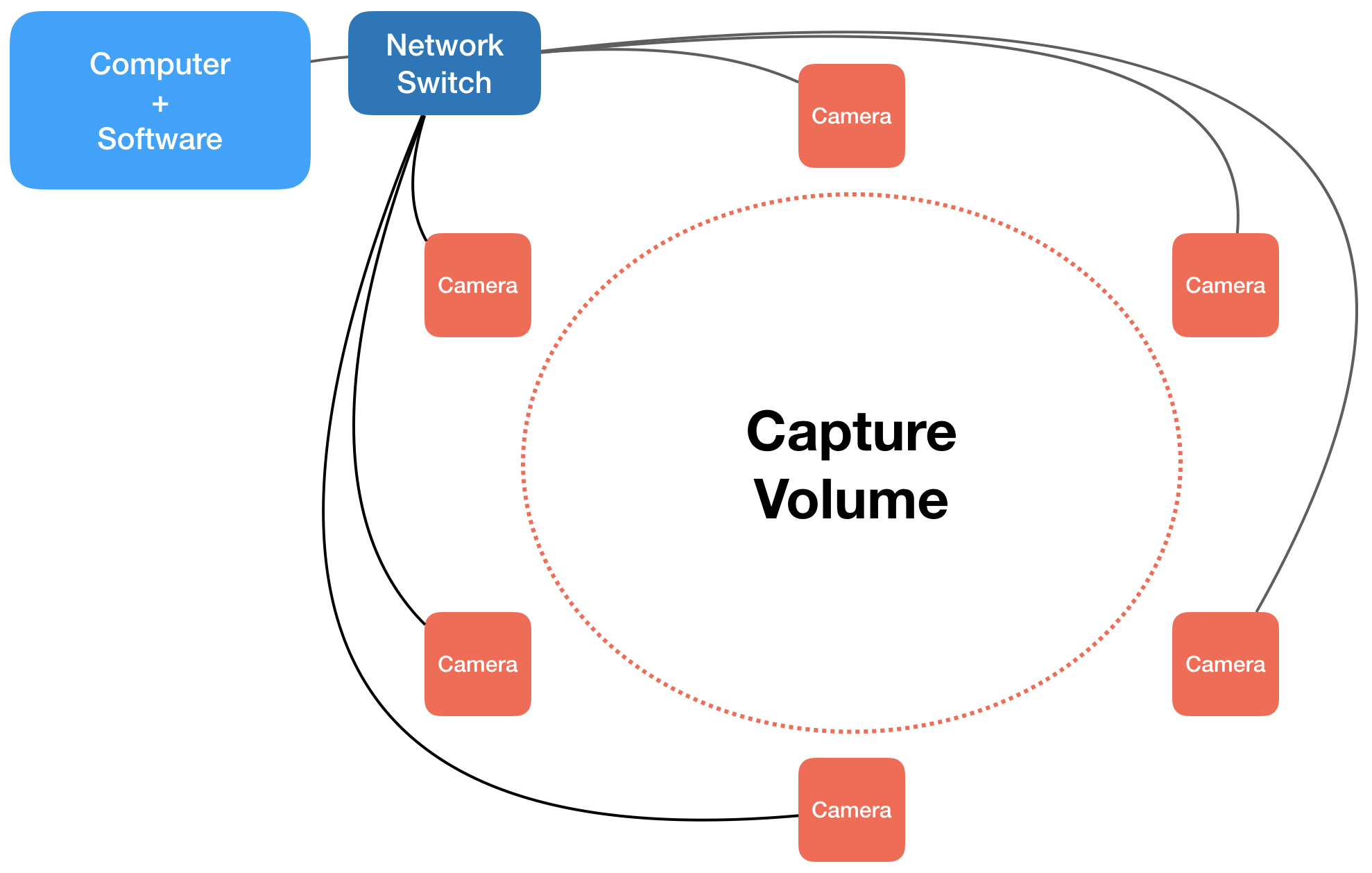
We currently have two setups. Both setups consist of a computer, a network switch and cameras. The connections look like this (number of cameras is variable):
The large interaction volume setup consists of:
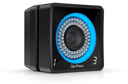
- 12 cameras of type Prime 13 (240 fps, 1280x1024)
- Two calibration devices: one wand (T shape), one ground plane (L shape)
- Computer
- Network switch
This is the Prime 13 camera (source: OptiTrack.com):
The small interaction volume setup consists of:
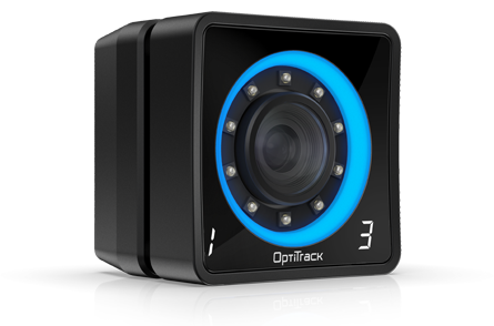
- 4 cameras of type Prime 13W (wide angle, 240 fps, 1280x1024)
- Calibration devices: one wand (T shape), one ground plane (L shape)
- Laptop
- Network switch
This is the Prime 13W camera (source: OptiTrack.com):
9.1.2 Software
The main software is Motive: Body by OptiTrack which one uses for
- calibration
- tracking objects and skeletons
- recording motion
- streaming motion data
- exporting motion data
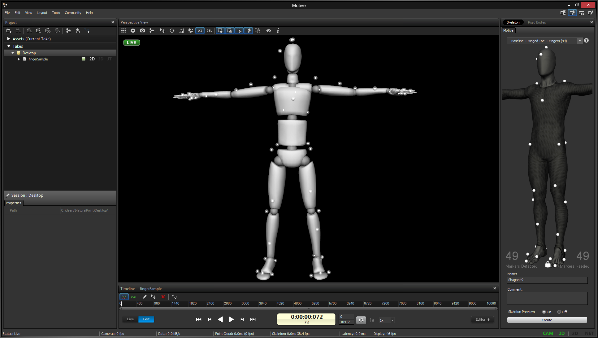
(source: OptiTrack.com)
9.1.3 Markers
Markers are little white objects coated with a retroreflective material. The cameras send out IR light which is reflected by the markers and detected by the cameras' IR sensors.
- 3 suits (2x size M, 1x size L): pants, jacket, head cap
- 2 pairs of foot wraps
- 2 gloves: including special hand markers and single finger markers
- facial marker set
9.2 Tracking
The overall lab configuration is quite easy. There is one computer that is connected to a network switch (flat box with many LEDs). The switch is connected to the 12 cameras via ethernet cables and additionally to the LAN.
When you are the first in the lab that day do the following:
- make sure the network switch has power (lights on), otherwise plug in power cable
- switch on computer
- start software Motive: Body
Next, we will describe calibration etc.
9.2.1 Setup
Try to remove shiny/reflective surfaces in the room (glas, metal, plastic ...). Otherwise, these surfaces will reflect markers and confuse the system.
Check the aim and focus of the cameras. In Motive you can select a particular camera and then, in the Devices Pane select under "Preset:Aiming" and you will see the b/w camera picture. Now you can move the camera such that the intended target/s are properly in view.
You can also change the focus using the focus tool:
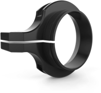
This is only necessary for the regular cameras (Prime 13), not for the wide angle cameras (Prime 13W).
9.2.2 Calibration
Calibration is a two-step process of wanding and setting the ground plane. Open View > Camera calibration pane. It is on the right side of the window and has two tabs - Calibration and Ground Plane - which correspond to the two calibration steps.
Step 1: Wanding
Find the calibration wand:
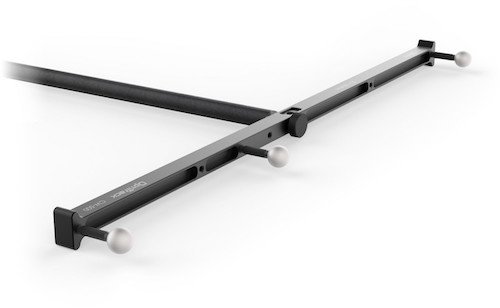
For wanding it is important to distinguish the wand type (there is a small white sticker where you can see it). Select the correct one under Calibration options / OptiWand:
- CWM-500: the bigger T-shaped stick
- CWM-250: the smaller one
First, we "mask" distracting signals by pressing "Clear Mask" and then "Mask Visible". Make sure the calibration wand is not visible at this point.
Now press Start Wanding move the stick around. You can see for each camera how many sample points they have collected (the higher the number the better). Wait until the "quality" is marked as "very high" or "excellent", then press Calculate.
Now the system starts computing and will ask you to accept the result and you can also save (export) the settings for later use.
Step 2: Setting the Ground Plane
Find the ground plane device:
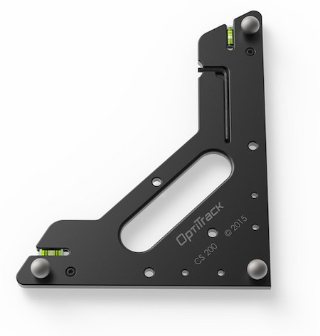
The next step is easy. Place the ground plane at the spot where you want your origin, usually on the floor somewhere in the center of your capture volume.
The change to the tab "Ground Plane" and press Set Ground Plane.
Now you can start tracking!
9.2.3 Rigid Bodies
You can attach a number of markers to an object and declare it a rigid body. The two requirements are:
- three or more markers (4+ is recommended, do not use too many)
- the constellation of markers is fixed (therefore "rigid")
- asymmetrical constellations are recommended
Create a rigid body
In the 3D perspective view, select all markers that should belong to the rigid body. Right click and select Rigid Body > Create from selected markers.
The new rigid body can be seen on the Assets Pane (menu View) where you can rename the rigid body by double-clicking on its name. Moreover, you can open the Properties Pane to fine-tune the rigid body.
Open the Rigid Body Pane to see real-time info of position and orientation.
9.2.4 Skeletons
Here, our description is especially sketchy and this is a tedious and complex process, so please look at the OptiTrack Handbook under "Motive Documentation > Skeleton Tracking".
Here you open the Skeletons Pane. The steps are:
- select a skeleton setup
- put on a suit and attach the markers according to the model (you can rotate and zoom the model in 3D)
- give the skeleton a name and press Create
You can view and delete the skeleton in the Assets Pane.
9.2.5 Streaming Data to Processing
We have written a Processing Client which can receive data live from the OptiTrack system. There is no official download page, please contact Prof. Kipp directly.
At the moment, it is receive marker and rigid body information in processing. We are working on applying this to skeletons as well.
You can also download the software package NatNet SDK which includes clients for C++, Python, C# and Matlab and a plugin for Maya.
To start streaming data open the Streaming Pane and select Show Advanced by clicking on the three dots in the upper right corner.
Make sure you have the following settings:
- Broadcast Frame Data: ON
- Local Interface: loopback
- Labeled Markers: ON
- Unlabeled Markers: OFF
- Rigid Bodies: ON